 |
||
|
|
||
| |||||||||||||||
|
|
 displacement, hopper volume, and location coordinates provided by a Global Positioning System.
These data are stored for later analysis.
Hopper Volume and Draft Determination. Volume of material in the hopper is calculated by
averaging the forward and aft ullage measurements and applying this value to an equation fitted to
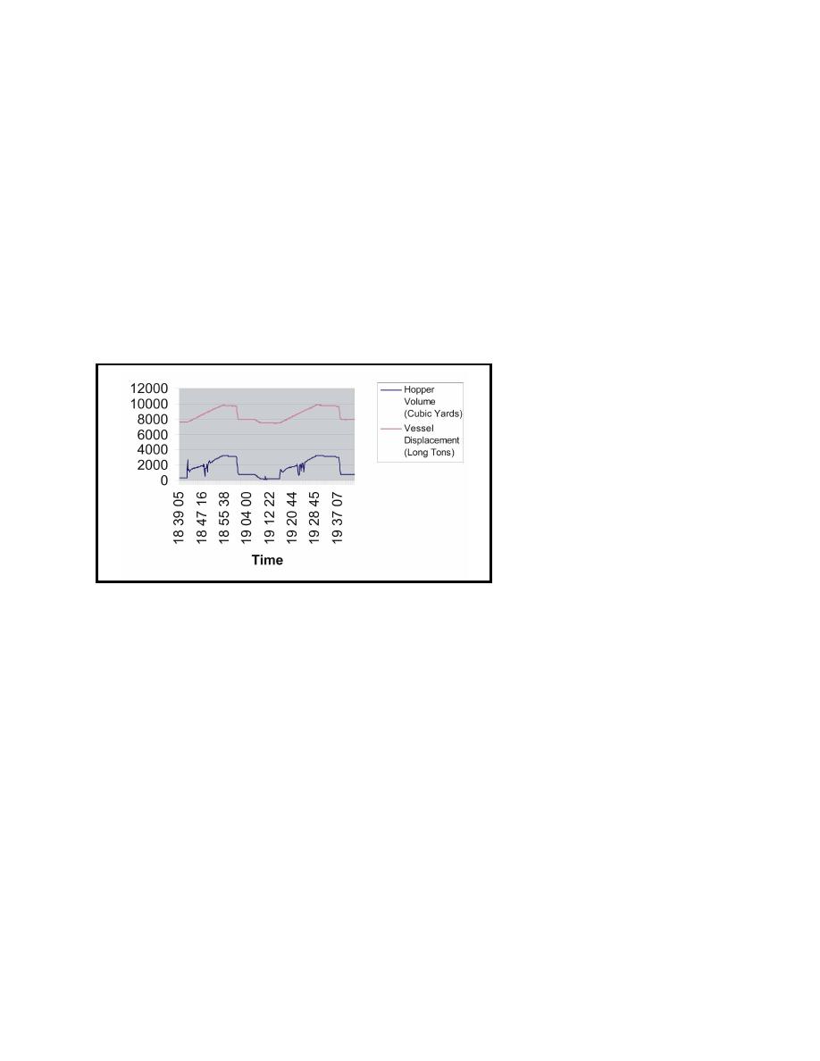
the ullage table values. A time-series plot of the hopper volume for the McFarland is shown in
Figure 9. The hopper volume variability during loading on this plot is explained by the fact that
the aft hopper level sensor reading is affected by inflow from the hopper distribution system.
Sometimes when dredging in noncohesive material, the bin water will not completely cover the
sediment load due to mounding above the water plane. Although the ullage sensors work as
intended, the level they report may not be indicative of the average surface level of the load,
introducing error into the volume calculation. This type of error is being investigated on the
McFarland, which often works in noncohesive material.
Weight of the hopper material is
determined by subtracting the un-
loaded vessel weight (including
the weight of residual water in the
hopper) from the loaded vessel
weight. These vessel weights, or
vessel displacement tonnages
(weight of the water volume dis-
placed by the hull), are calculated
by applying draft measurements to
the vessel curves of form. These
curves equate vessel draft to dis-
placement tonnage (time-series
Figure 9.
plot shown in Figure 9).
TDS QUALITY ASSURANCE TESTS: Quality assurance tests are tests that are conducted to
verify the accuracy and/or consistency of sensor or algorithm outputs.
Ullage Measurements. To date, ultrasonic and radar ullage measurements have compared well
with manual tape measurements when the surface of the hopper material consists of just slurry or
water. However, when foam has been encountered on the hopper material surface, the acoustic or
radar pulse is reflected off of the bubble interface instead of the dredged material surface. The
amount of error introduced into the ullage measurement depends on the thickness of the foam.
Water Tests. One of the TDS quality assurance tests being conducted on the McFarland and
calculate the average specific gravity of the water therein and compare it to an average value
determined from samples that are taken from the hopper and analyzed. Water samples retrieved
from the hopper at various locations and depths are being measured with a temperature-compensated
hand refractometer capable of measuring specific gravity to an accuracy of 0.001. The sensor-
measured hopper material specific gravity is calculated by dividing the hopper volume by its weight,
|
|
Privacy Statement - Press Release - Copyright Information. - Contact Us - Support Integrated Publishing |
