 |
||
|
|
||
|
Page Title:
Table 2. Hydraulic Conductivities of Various Soil Liners |
||
| |||||||||||||||
|
|
 ERDC TN-DOER-R6
December 2004
employed while maintaining sufficient control of leachate. In most situations, uncontaminated fine-
grained, low-permeability material is readily available for use in liner systems. Initial excavation for
dikes or for site preparation will typically remove topsoil and possibly a layer of foundation soil. The
bottom of the excavation may then be compacted to an optimal density through use of a sheeps-foot
roller, vibratory roller, or other type of compaction equipment. If additional soil liner thickness is
required, lifts of additional soil approximately 6 in. in depth should be applied, ensuring that each lift is
well connected to previous and subsequent lifts through the use of sheeps-foot rollers. It is critical that
optimum water content be maintained throughout the liner construction operation. Further discussion of
compactive effort and moisture content requirements for optimization of hydraulic conductivity and shear
strength of soil liner systems are provided in EM 1110-1-502 (USACE 1994), EPA/625/6-88/018
(USEPA 1988a), EPA/600/2-88/052 (USEPA 1988b), 57 FR 3462 (USEPA 1992a), and in later sections
of this document.
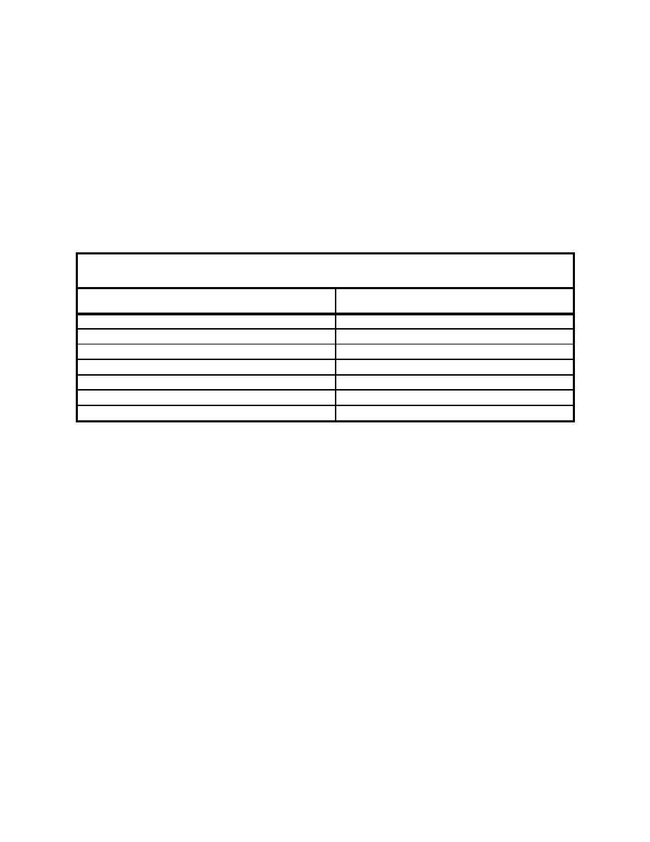
Table 2
Hydraulic Conductivities of Various Soil Liners
Unified Soil Classification System (USCS) or Liner
Hydraulic Conductivity (cm/s)
Classification
10-9 to 10-6 (Fetter 2001)
Clay
10-7 (Schroeder et al. 1994)
Barrier Soil
6.8x10⁻⁷ (Schroeder et al. 1994)
CH (Inorganic Clay of high plasticity)
7.8x10⁻⁷ (Schroeder et al. 1994)
SC (Sand Clay)
10-9 to 10-7 (Giroud et al. 1997)
Compacted Soil (see ref. for site specifics)
3x10⁻⁹ (Schroeder et al. 1994)
Bentonite Mat (0.6 cm)
10-10 to 10-9 (Giroud et al. 1997)
Colloidal Clay
Clean Dredged Material. An inexpensive and efficient liner material that should not be overlooked in
the design of CDFs is clean dredged material. When allowed to settle and condense, fine-grained material
dredged from rivers and harbors can reach permeabilities as low as 10-7 to 10-10 cm/s (Giroud et al. 1997,
Schroeder et al. 1994). By most standards, this range of liner permeability is acceptable for service as
hydraulic barriers.
With this option, areas of the channel that contain uncontaminated material are dredged first, and the
material is pumped into the CDF. Following dewatering and consolidation, clean fine-grained dredged
material can form a low-permeability layer. If application of fine-grained dredged material occurs after
placement and compaction of a low-permeability subsoil liner, clean fine-grained dredged material will
add to the total effective thickness of the liner system. Besides possessing an enhanced hydraulic barrier
following consolidation, the dredged material often contains appreciable amounts of organic carbon,
which increases the sorption capacity of the liner system, further retarding the transport of hydrophobic
organic contaminants through the liner system. The Primary Consolidation, Secondary Compression, and
Desiccation of Dredged Fill (PSDDF) computer program (Stark 1996) provides a means to quantify
consolidation and settlement of dredged material and its impact on hydraulic conductivity.
Modified Soils/Dredged Material. It may be necessary to site CDFs where soils and dredged material
with high hydraulic conductivity (e.g., silts or sand) are ubiquitous as the natural material. Their use as
liner components is limited by their hydraulic conductivity. Examples of other materials that possess
high hydraulic conductivities are provided in Table 3. The preferred hydraulic conductivity for barrier
systems is 10-5 to 10-8 cm/s; thus, either the native soil must be modified to reduce its hydraulic
conductivity to acceptable levels, a borrow (offsite) material of lower hydraulic conductivity must be
brought in and installed, or more sophisticated liner systems (e.g., geomembranes) must be employed.
10
|
|
Privacy Statement - Press Release - Copyright Information. - Contact Us - Support Integrated Publishing |
