 |
||
|
|
||
|
Page Title:
Figure 6. Example of potential safety hazard due to location of weir and boards |
||
| |||||||||||||||
|
|
 ERDC TN-DOER-T3
January 2001
Figure 6. Example of potential safety hazard due
Figure 7. Example of unlevel weir boards and
to location of weir and boards
uneven effluent withdrawal across
boards
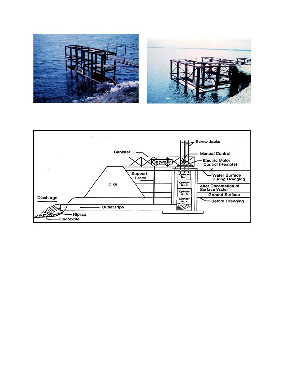
Figure 8. Schematic profile diagram, telescoping weir concept
From 1986 to 1994, the U.S. Army Engineer Waterways Experiment Station (WES), Vicksburg,
MS, and the U.S. Army Engineer District, Norfolk, conceived, designed, constructed, and tested a
1/4-scale model of the first telescoping weir. The concept was originally drafted in 1986, a prototype
model was constructed at WES in 1992, and the first full-size prototype telescoping weir was con-
structed and installed at Craney Island CDF (placement site) in 1996 (Fowler, Vann, and Woodward
1999) (Figure 9).
The major components of the telescoping weir include the following:
Three cylindrical telescoping sections, with the upper section forming the crest of the weir.
Seals to prevent the intrusion of sediment into the weir.
A base section to receive the weir flow and to route it to a discharge pipe.
4
|
|
Privacy Statement - Press Release - Copyright Information. - Contact Us - Support Integrated Publishing |
