 |
||
|
|
||
|
Page Title:
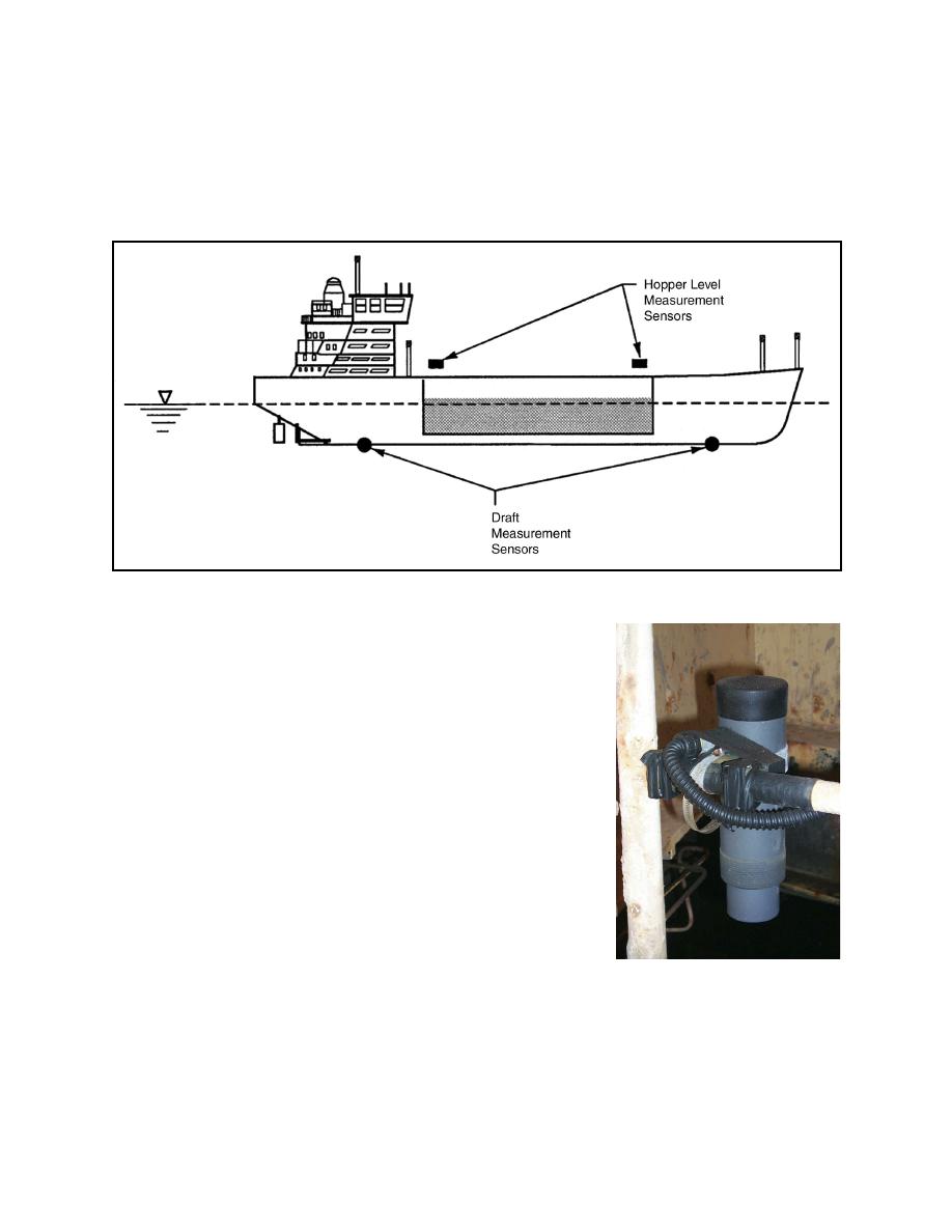
Figure 4. Hopper level and draft sensors |
||
| |||||||||||||||
|
|
 ERDC TN-DOER-T6
September 2004
possible to minimize trim-induced error (Welp and Rosati 2000). Sensor specifications state an
accuracy of 0.25 percent of the measurement range (2 to 50 ft) with no temperature gradient.
This measurement method's accuracy is affected by environmental factors (i.e., temperature,
incident angle, surface composition, humidity, presence of nearby structures, and sediment
buildup on the transducer by slurry spray).
Figure 4.
Hopper level and draft sensors
Experience on the McFarland and dredge Wheeler (Jorgeson
and Scott 1994) illustrates that proper placement of these
transducers is critical to optimizing operating efficiency and
accuracy for these types of sensors. On both dredges, the
sensors were located above the maximum hopper slurry level
and away from the distribution points to minimize direct
contact with splashing and spray. Hopper configuration aspects
(i.e. being open or closed, sloping sides, etc.) and the presence
of piping, auxiliary equipment, and structural members can
impact placement alternatives of these sensors. Periodic
cleaning of the transducers on the dredge McFarland assisted in
minimizing error from sediment deposited on the transducer by
spray, but when a sufficient layer of foam was generated on the
slurry surface, inaccurate readings were recorded until the foam
dissipated (this type of foam is illustrated in Figure 6) . This
error component has been observed on other dredges that use
the Silent Inspector.
Figure 5.
An ultrasonic
transducer mounted
over the dredge
An additional measurement error component is introduced
McFarland's hopper
when using ultra-sonic sensors to measure sand load volumes
with a layer of water overlaying the settled sand. The ultra-sonic pulse reflects off the
supernatant water, not the sand surface, thereby introducing error proportional to the water
layer's thickness. Another measurement error component is encountered when an uneven
8
|
|
Privacy Statement - Press Release - Copyright Information. - Contact Us - Support Integrated Publishing |
