 |
||
|
|
||
| |||||||||||||||
|
|
 mound was created by point dumping at a taut-moored buoy, the New Eng-
land District will place the majority (say 65 to 70 percent) of the capping
material in similar fashion. However, the capping material is placed
within 50 to 75 m of the buoy as opposed to the 25-m limit used for the
contaminated material. The remaining 30 to 35 percent of the material is
spread around the outer edge of the mound, say 100 to 150 m from the
buoy.
Spreading over large areas
For larger projects, a series of specific lanes can be defined to spread
the capping material. This technique is generally used when the sand is
sprinkled. The sprinkling can be accomplished by cracking the hull of the
barge or split-hull hopper dredge or by direct pumpout from a hopper
through over-the-side pipes. The most straight-forward method to deter-
mine lane spacing for the cracked-hull technique is to compute the foot-
print from an individual load using either the Multiple Dump Fate of
Dredged Material (MDFATE) or Short-Term Fate (STFATE) model (see
Chapter 6 and Appendixes D and E). Of interest will be the footprint's
maximum thickness, maximum width, and width at 0.5 the maximum
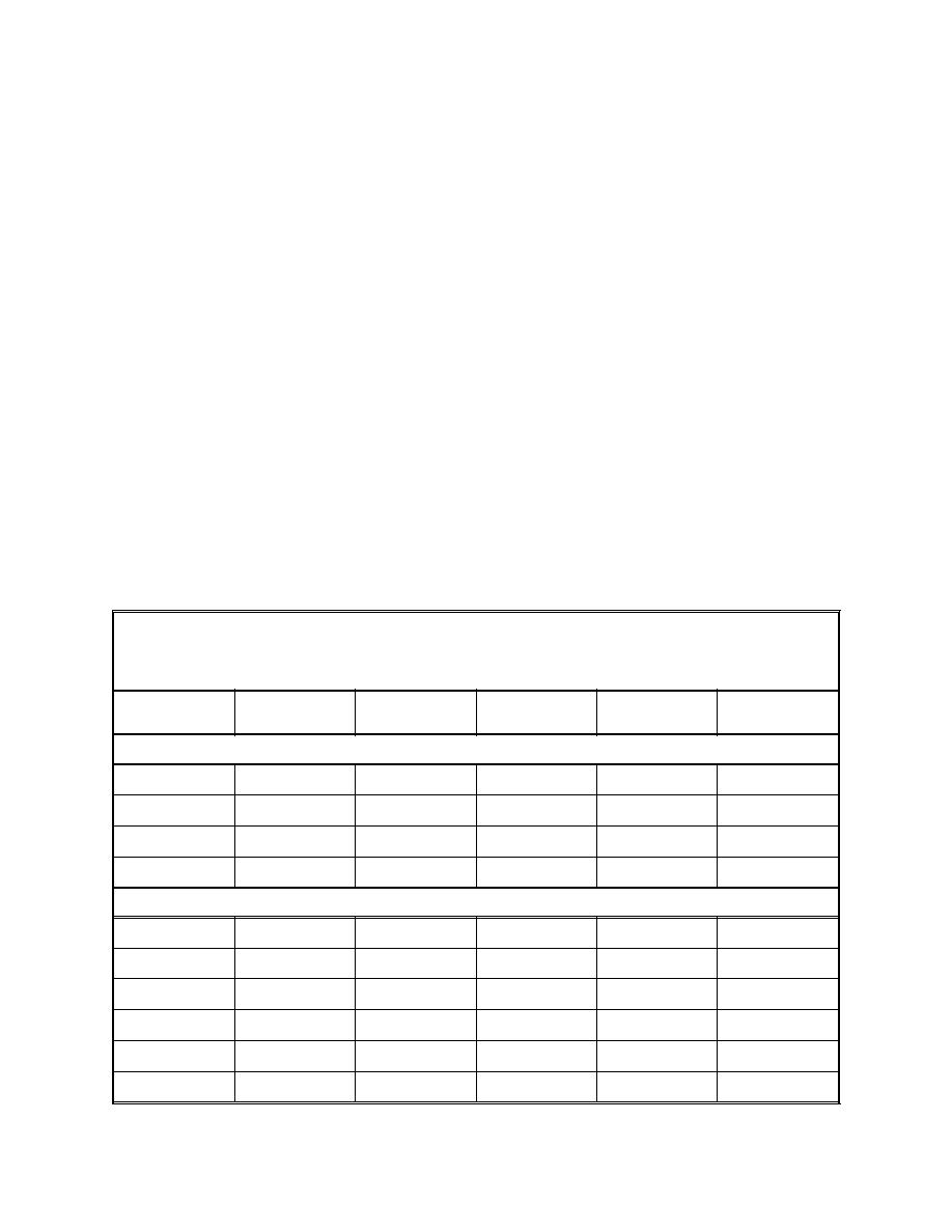
thickness. Table 5 shows the results of MDFATE runs used to design the
capping operation for the Port Newark/Elizabeth project. Based on this
information, disposal lanes 30 m (100 ft) wide, or approximately equal to
the maximum width of the footprint predicted by the model lanes, were
Table 5
Summary of Modeling Results for Capping Contaminated Sediments Using the
Split-Hull Hopper Dredge Dodge Island and Hopper Barge Long Island
Dredge Speed
Disposal Time
Maximum
Maximum Width
Width at 0.5 Max
Disposal Type
m/s
min
Thickness, cm
m
Thickness, m
Split-Hull Hopper Dredge Dodge Island
Cracked hull
1.54
20
4.3
32.0
18.3
Cracked hull
1.54
30
2.7
32.0
18.3
Cracked hull
1.03
20
6.4
41.0
18.8
Cracked hull
1.03
30
4.3
32.0
18.3
Hopper Barge Long Island
Counterflow
0.51
120
7.3
155.4
64.0
Counterflow
1.03
120
3.0
155.4
82.2
Counterflow
0.51
180
4.9
137.2
64.0
Counterflow
1.03
180
2.0
137.2
82.2
Counterflow
0.51
180
4.9
137.2
64.0
Counterflow
1.03
180
2.0
137.2
82.2
47
Chapter 5 Equipment and Placement Techniques
|
|
Privacy Statement - Press Release - Copyright Information. - Contact Us - Support Integrated Publishing |
