 |
||
|
|
||
| |||||||||||||||
|
|
 ERDC TN-DOER-N7
August 2000
to 1,026 to 1,270 wet-g/L density). However, concentrations at the upper end of this range may not
be navigable, and the term `fluid mud' used here is not meant to imply navigability. Solids in the
pipeline are generally about 15 percent by weight or 150-200 g/L (Schubel et al. 1978).
Underflow spreading controls the configuration of the final deposit. Limited observations indicate
that the final deposit is a series of strata laid down as the underflow shifts and grows larger in
response to bottom topography. Maximum deposit thickness was about 0.3 m (1 ft) for a typical
2-day disposal operation in Mobile Bay and about 1.8 m (6 ft) for a 10-day disposal in the James
River (Nichols and Thompson 1978).
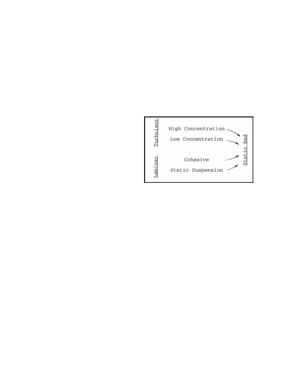
Underflow Classification. A fluid mud underflow can be characterized by its density, and speed,
and can behave as a turbulent turbidity current, or laminar slowly-spreading underflow, as shown
in Figure 2. The turbulent or laminar condition
is critical to underflow characteristics and con-
centrations. Laminar flows have smooth parti-
cle trajectories while turbulent flows have
chaotic motions, in addition to the mean flow,
which change flow properties. Turbulent un-
derflows or turbidity currents have lower fric-
tion and a characteristic billowing head just
behind their leading edge. Turbulent under-
flows have velocity profiles that, unlike open-
channel flows, have highest velocities near the
bed. Since turbulent underflows generally en- Figure 2. An underflow classification scheme using
local flow and concentration conditions
train ambient water, they grow vertically and
tend to have lower concentrations than laminar
underflows. Since one goal is to avoid turbidity generation, low-density turbulent underflows are
to be avoided in most cases as they are readily entrained into the overlying flow. Entrainment of
water into the underflow, and growth in underflow thickness, can occur under turbulent underflow
conditions. As noted earlier, density and viscosity differences between the fluid mud and the
overlying water column inhibit entrainment.
Pipeline discharges originate as turbulent flows, but empirical evidence suggest that they transition
to laminar underflow after spreading a short distance along a relatively flat bottom (Thevenot et al.
1992). Deceleration brings a low- or high-concentration turbulent underflow into the laminar
regime. Slow-spreading laminar undeflows have a velocity profile with 0 velocity at the bed, a
concentrated zone of relatively high fluid shear, and often a plug-flow or 0-shear zone near the
surface. Further description of laminar underflow properties will be provided in the next section.
Laminar underflows do not entrain ambient water. In fact, evidence suggests that they increase in
concentration as they spread, apparently as the result of settling. Underflows of both turbulent and
laminar types can be entrained into the overlying water column under certain conditions. Static beds
are generally formed by deposition from any of the underflow types as shown in Figure 2.
4
|
|
Privacy Statement - Press Release - Copyright Information. - Contact Us - Support Integrated Publishing |