 |
||
|
|
||
| |||||||||||||||
|
|
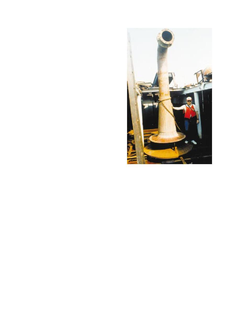
 Design specifications for this sub-
merged diffuser system are available
(Neal, Henry, and Greene 1978;
Palermo, in preparation).
A variation of the DMRP diffuser
design was used in an equipment
demonstration at Calumet Harbor, Illi-
nois. Although not constructed to the
DMRP specifications, this diffuser
significantly reduced pipeline exit ve-
locity, confined the discharged mate-
rial to the lower portion of the water
column, and reduced suspended sol-
ids in the upper portion of the water
column (Hayes, McLellan, and Truitt
1988). Diffusers have been con-
structed using the DMRP design and
used at a habitat creation project in
the Chesapeake Bay (Earhart, Clark,
and Shipley 1988) and at a Superfund
pilot dredging project at New Bed-
ford Harbor, Massachusetts, involv-
ing subaqueous capping (USACE
1990). At the Chesapeake Bay site,
the diffuser was used to effectively
achieve dredged material mounding
prior to placement of a layer of oys-
ter shell to provide substrate for at-
tachment of oyster spat. At the New
Bedford site, the diffuser was used to
Figure 9. Submerged diffuser
place contaminated sediment in an
excavated subaqueous cell and was effective in reducing sediment resus-
pension and in controlling placement of contaminated sediment. How-
ever, capping operations were started immediately, and positioning of the
diffuser within 2 ft of the contaminated sediment layer resulted in mixing
of cap sediment with contaminated sediment. These results indicate the
need for a high degree of control when capping newly placed slurry with a
diffuser and the need for adequate time to allow for some self-weight con-
solidation of slurry material prior to capping. Diffusers have also been
successfully used to place and cap contaminated sediments at projects in
Rotterdam Harbor in the Netherlands (d'Angremond, de Jong, and de
Waard 1986) and in Antwerp Harbor in Belgium (Van Wijck and Smits
1991).
Sand spreader barge
Specialized equipment for hydraulic spreading of sand for capping has
been used by the Japanese (Kikegawa 1983; Sanderson and McKnight
1986). This equipment employs the basic features of a hydraulic dredge
with submerged discharge (Figure 10). Material is brought to the spreader
by barge, where water is added to slurry the sand. The spreader then pumps
35
Chapter 5 Equipment and Placement Techniques
|
|
Privacy Statement - Press Release - Copyright Information. - Contact Us - Support Integrated Publishing |