 |
||
|
|
||
|
Page Title:
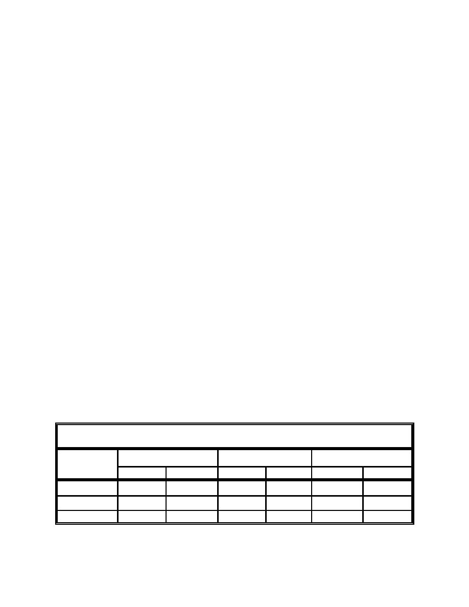
Table H1. Lengths Associated with Generic-Capped Mound in Figure H3 |
||
| |||||||||||||||
|
|
 where
VM = volume of cap material over dredged material mound
VCA = volume of material in cap apron
VT = total volume of cap material
tpc = thickness of primary cap
tta = thickness of cap at toe of mound apron
tc = change in cap thickness over apron (tpc - tta)
r1 , r2 = long, short radius of ellipse
= subscript for dredged material mound
M
= subscript for inner dredged material mound (crest, inner flank and
IM
outer flank)
= subscript for total capped surface
TC
m = slope of change in cap thickness (i.e., 1:100!m=0.01)
The volume of cap material overlying the inner and outer flanks may be
calculated as part of the overall dredged material mound cap volume calcula-
tions. When there is no change in cap thickness over the mound apron as in
Figure H1, the cap volume over the mound apron may also be included in the
overall dredged material mound cap volume calculations. To demonstrate,
assume a generic circular mound having a relief of 2.1 m (7 ft) with cap 0.9 m
(3 ft) thick is created (Figure H3). Approximate average inner flank, outer flank,
and apron slopes are 1:50, 1:400, and 1:2000, respectively. Table H1 shows that
for this example, the horizontal length and slope length are nearly equal, so use
of the horizontal length in cap volume calculation is justified. For steeper slopes
and/or higher mound relief, this assumption should be verified.
Table H1
Lengths Associated with Generic-Capped Mound in Figure H3
Vertical Length
Horizontal Length
Slope Length
m
ft
m
ft
m
ft
A - B Inner Flank
0.9
3
46
150
46.009
150.03
B - C Inner Flank
0.9
3
366
1,200
366.0011
1,200.00375
C - D Apron
0.3
1
610
2,000
610.000074
2,000.00025
H6
Appendix H Level-Bottom Capping Projects
|
|
Privacy Statement - Press Release - Copyright Information. - Contact Us - Support Integrated Publishing |