 |
||
|
|
||
|
Page Title:
Parrot's Beak, Rotterdam CDF Liner and Leachate Collection |
||
| |||||||||||||||
|
|
 ERDC TN-DOER-C18
August 2000
The silt mounds themselves are essentially upland CDFs, acting as covers
constructed over previously used conventional CDFs. A double seal liner is
installed at the base of the silt mound (essentially on top of the old CDF),
consisting of 2.5-mm-thick HDPE, heat-sealed, with a 1.5-m-thick layer of
compacted silt. Dewatered dredged material is placed in layers with interme-
diate layers of separated sand acting as drainage layers. A double seal is also
To view figure
larger, click here
installed as a cover layer, with a topsoil layer for planting a vegetative cover.
A cross-section of this arrangement is shown in Figure 11.
Figure 11
Parrot's Beak, Rotterdam CDF Liner and Leachate Collection: The
Papegaaiebek (Parrot's Beak) site in Rotterdam, The Netherlands, is a 40-ha
upland CDF specially designed for highly contaminated dredged material from
Rotterdam Harbor. The site has been filled with approximately 1.5 million
cubic meters of fine-grained material, and hydraulic pipeline dredges or
To view figure
hydraulic off-loaders were used for the filling. A plan view of the site and a
larger, click here
typical cross-section of the dike used are shown in Figure 12.
Figure 12
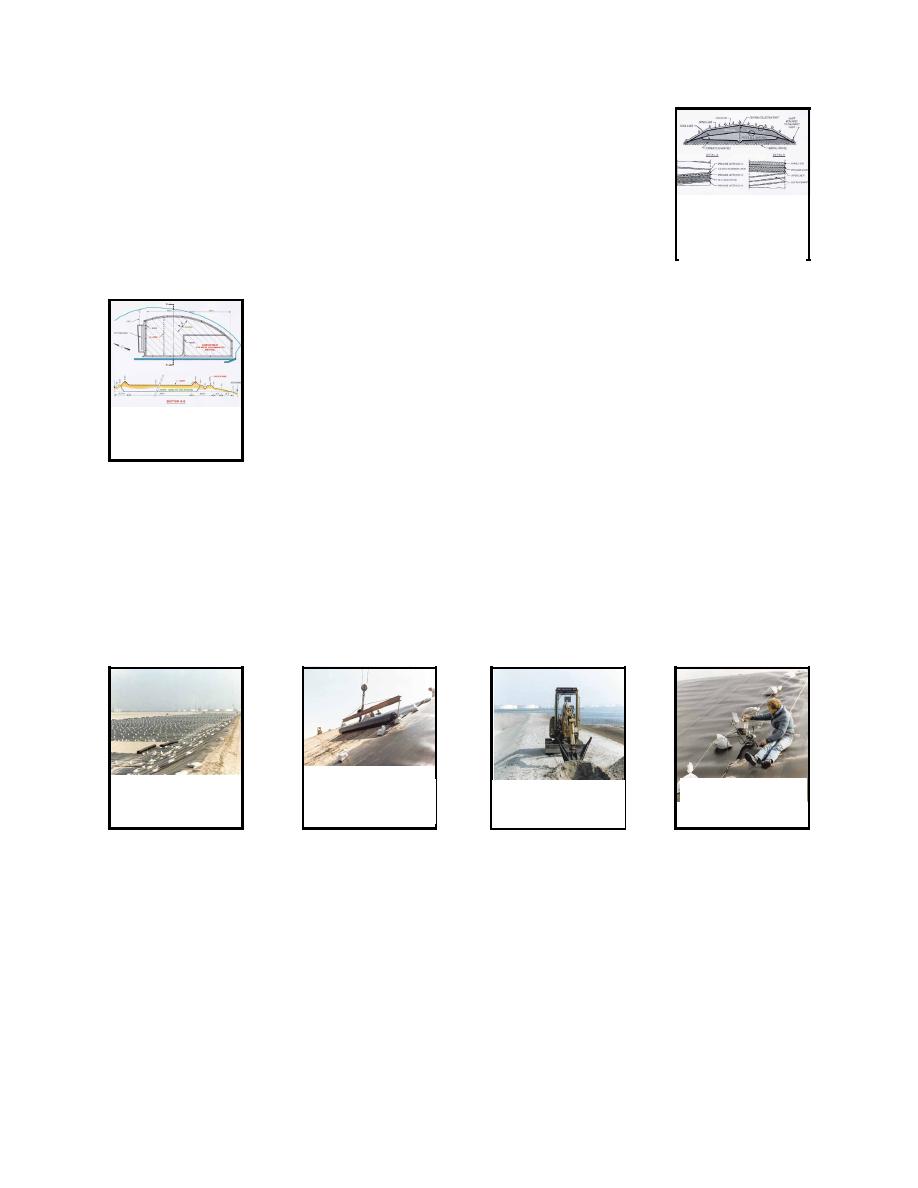
This CDF was designed with a liner and leachate collection system. The liner for Parrot's Beak
consisted of 2-mm-thick HDPE sheeting. The liner material was placed in overlapping strips (see
Figures 13 and 14), extending across the bottom of the basin and onto the inside face of the dike.
A crane was used to unroll the strips, which were then held in place with sandbags. The edge of
the liner was anchored in a trench excavated along the dike crest (Figure 15). Seams were then
heat-welded (Figure 16). The leachate collection system consisted of 100-mm-diam perforated pipe
placed at 50-m spacings.
To view figure
To view figure
To view figure
To view figure
larger, click here
larger, click here
larger, click here
larger, click here
Figure 13
Figure 14
Figure 15
Figure 16
Once dredged material was initially placed in the site, an inner compartment was constructed for
the most highly contaminated sediment, separated from the remainder of the CDF by an interior
filtration dike. Clean fine-grained dredged material was used to form the main berm for the interior
dike and was left in a layer above the membrane within the interior compartment. The upper portion
of the interior dike section consisted of a sand core with geotextile placed on the inside face which
acted as a filter for excess water flowing from the interior compartment to the main CDF.
Venice Lagoon CDF "Diaphragm" Liner and Cover. A confined site with special lateral
containment measures was constructed as a part of the overall remediation of the Venice, Italy,
9
|
|
Privacy Statement - Press Release - Copyright Information. - Contact Us - Support Integrated Publishing |
